Project Goal
The goal of our project is to implement Hamming(7, 4) (7 bits per message, 4 of them are data bits) error correction in simulation. We will implement a module that encodes 4 bits of data into a 7-bit message and a module that receives a 7-bit message and decodes the 4 data bits.
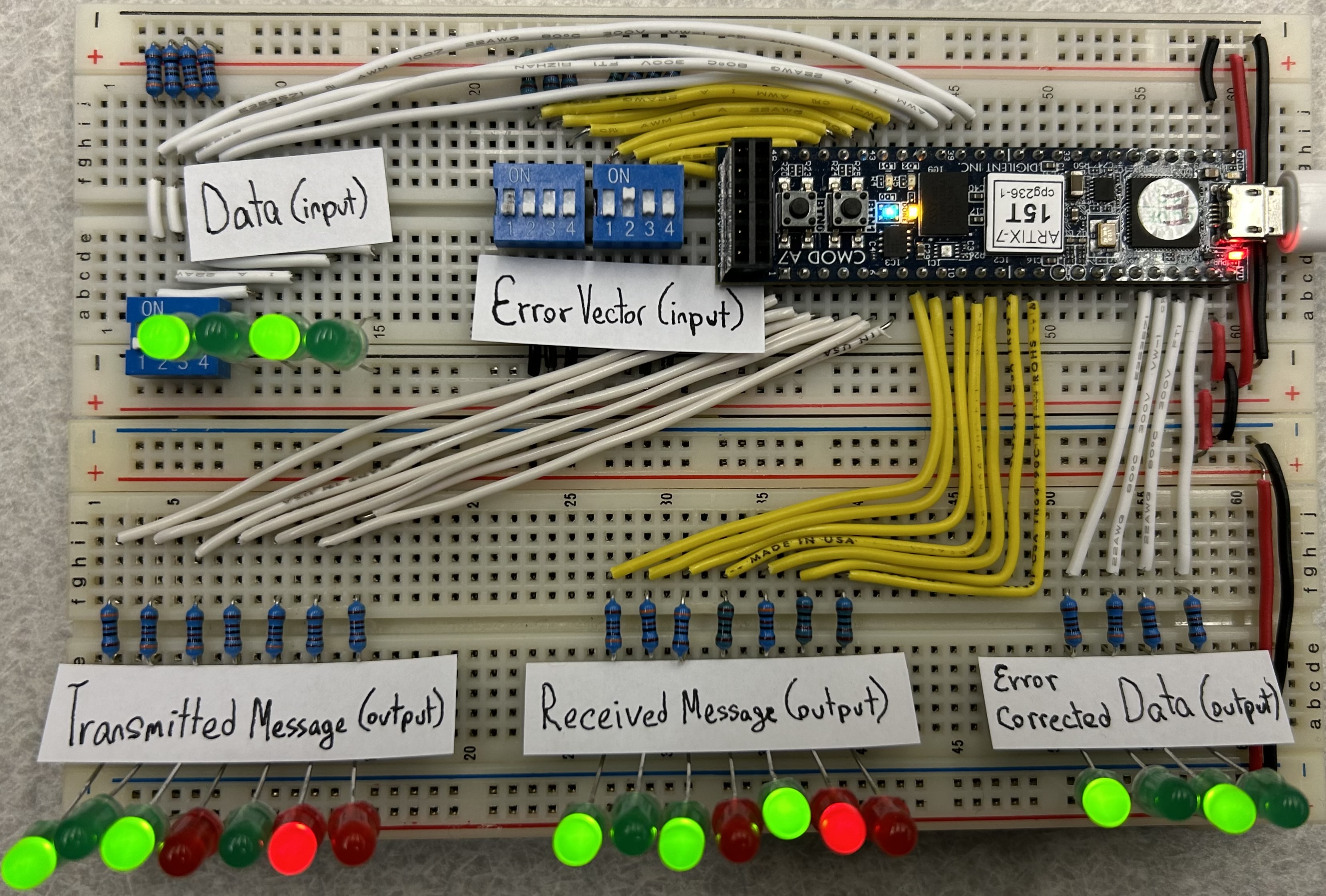
A stretch goal is to visualize the stages of error correction using hardware. Our implementation will use switches to set the original 4-bit message and to introduce errors into the encoded message, simulating a noisy transmission channel. An FPGA will be used to set the three parity bits and decode the received message. We intend to use LEDs to visualize the message as it is encoded and decoded.
What are Hamming Codes?
Hamming Codes are self-correcting codes. The premise is that messages sent from a sender to a receiver across a potentially noisy channel can become distorted. The motivation behind self-correcting codes is to identify if errors occurred during the transmission of a message and to fix them, so that the recipient sees the intended message. We have chosen to implement a Hamming code, which uses a series of strategically placed parity checks to identify if an error has occurred during transmission; parity bits are used to maintain an even number of 1’s in specific sections of the code, such that narrowing down which sections of the code contain an error (odd number of 1’s) upon receipt of the message can identify and correct up to one bit error.

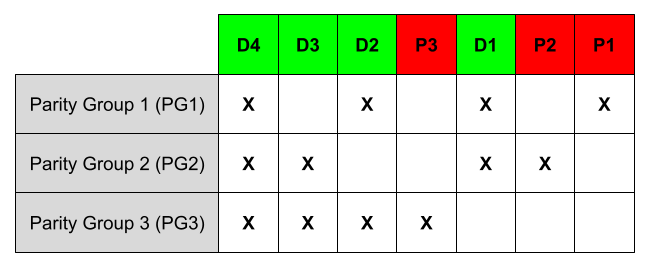
In the diagram above, Xs are used to indicate which sections of the encoded message are grouped together, with each row representing a group; each of these groups includes one parity bit. Any single error introduced into a message during transmission can be detected and corrected because each bit is part of a unique subset of the parity groups.
Our Schematics
Encoding

Decoding

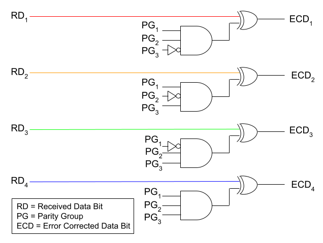
The parity groups come from checking the parity bit and the data bits together have an even number of 1’s. PG1 comes from checking the bitstring created by P1, RD1, RD2, and RD4 has an even number of 1’s: it will be 0 if they do, and 1 if they do not. The same is true for PG2 with P2, RD1, RD3, and RD4 and for PG3 with P3, RD2, RD3, and RD4.
Implementation Details
We created two submodules for this task: an encoder and decoder. The encoder takes four data bits and outputs a seven bit message, which combines data and parity bits. The decoder takes a seven bit received message and outputs data after correcting up to one error in the message.
Our main module has two inputs: four bits of data and a seven bit error vector. It puts the data through the encoder to receive a message, then adds the error vector to the message to form a received message. The received message is placed through the decoder to retrieve the original message. We output our transmitted message, received message, and error-corrected data to be able to show all of them with LEDs.
Note: in our code, we output rx_msg_bar and similar to allow our LED display to be powered by the power rail rather than a pin on the FPGA due to current limits on pins.
Bill of Materials
- 1 Cmod A7
- 16 Green LEDs
- 16 301 Ω Resistors
- 6 Red LEDs
- 13 1 kΩ Resistors (6 for red LEDs + 7 for error vector switch)
- 3 DIP Switches
Breadboard Layout

Video Walkthrough
References
Dipperstein, M. (2018, December 27). Hamming (7,4) code discussion and implementation. Retrieved December 16, 2022, from https://michaeldipperstein.github.io/hamming.html
Eater, B. (2020). What is error correction? Hamming codes in hardware. YouTube. Retrieved December 16, 2022, from https://www.youtube.com/watch?v=h0jloehRKas.